Transformer Parallel Operation & System Compatibility: Engineering and Procurement Guide
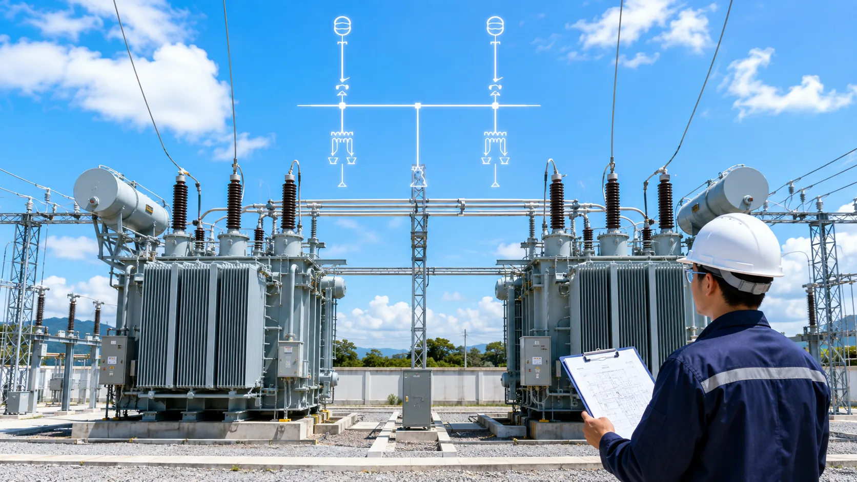
Why two individually healthy transformers may still be incompatible
Parallel operation connects two voltage sources to one bus. Each transformer therefore sees the other unit’s voltage magnitude, phase relationship, internal impedance and neutral/grounding network. A mismatch can appear as circulating current, unequal loading, nuisance protection operation or a bus tie that should not be closed.
Nameplate voltage, kVA and a FAT “PASS” are only parts of the decision. Compatibility has to be reviewed as a system condition that includes the existing unit, the new unit, the bus, protection and the final site wiring.
Seven compatibility layers to review
1. Voltage and ratio: nominal secondary voltage is not the same as actual no-load voltage at the operating tap.
2. Phase relationship: vector group or connection, polarity, phase sequence and phase displacement must be compatible at the paralleling point.
3. Impedance and load sharing: lower equivalent impedance tends to carry more current; impedance angle can also affect real/reactive sharing.
4. Capacity and thermal margin: different kVA ratings can be workable, but the smaller unit must not reach its thermal limit first.
5. Neutral, grounding and zero sequence: winding connection and grounding define whether and where zero-sequence current can flow.
6. Protection and control: differential, overcurrent, ground-fault protection, CT circuits, interlocks and energization logic must match the operating mode.
7. Site facts: phase check, phase sequence, actual tap position, terminal wiring and protection status must be verified before the bus tie is closed.
Hard stop items versus calculation items
Incompatible phase displacement, phase sequence or polarity is normally a hard stop. These are not conditions that can be “balanced out” by changing the load.
Ratio/tap differences require an assessment of voltage difference and combined impedance because they can create circulating current. Impedance and kVA differences require load-sharing calculations at the maximum planned operating load. Grounding and protection require a project-specific system study and approved one-line diagram.
Procurement inputs that should be collected early
For the existing transformer, collect the nameplate, one-line diagram, kVA, primary/secondary voltages, current tap position, vector group or phasor/connection diagram, percent impedance, grounding arrangement, intended bus-tie operating mode and major protection interfaces.
For the new transformer, require a complete tap table, connection/terminal drawings, guaranteed impedance, relevant routine-test results and the agreed neutral/protection interfaces. Any item owned by the EPC, consultant or protection engineer should be shown as an open item instead of being hidden behind a generic “suitable for parallel operation” statement.
What the commissioning record should prove
Keep the approved drawings, both nameplates, actual tap positions, phase-sequence/phase-check results, critical secondary-circuit and protection status, neutral/grounding confirmation, bus-tie operating procedure and an initial current/voltage/temperature baseline after first paralleling.
That baseline becomes valuable later if the two units begin to show unequal current, temperature differences, neutral-current changes or protection events.
Procurement / engineering execution checklist
| Role | Core information / action |
|---|---|
| Buyer / EPC | Existing nameplate, one-line, kVA, voltages, tap, vector/connection, %Z, grounding, protection and operating mode. |
| Supplier | New-unit tap table, connection/terminal drawings, guaranteed %Z, routine-test data and interface details. |
| Site / Commissioning | Actual taps, phase sequence/check, grounding, CT/protection status, bus-tie procedure and first-parallel baseline. |
Both Transformers Passed. Why Did We Still Refuse to Close the Bus Tie?
Frequently Asked Questions
Do identical transformer models automatically parallel safely?
No. Identical models improve the chance that parameters match, but actual tap position, phase relationship, impedance, grounding, protection and field wiring still require verification.
If both secondaries measure 480 V, can the bus tie be closed?
Not on that reading alone. Phase relationship, sequence, actual ratio/tap, impedance, grounding and protection must also be confirmed.
Can transformers with different kVA ratings operate in parallel?
Potentially, but the load split and thermal margin of each unit must be calculated from actual parameters.
Does FAT prove parallel compatibility?
FAT provides key evidence such as ratio, connection and impedance. Final compatibility also depends on the existing transformer, system design and site condition.
- Power Transformers and Protection Q&A — operation, paralleling, ratio, vector group, impedance and inrush chapters
- Electrical Engineer’s Handbook, 4th ed. — system connection, transformer impedance and substation engineering
- Relay Protection Technical Supervision Manual — transformer inrush, differential protection and commissioning checks
- Fundamentals of Power Systems — neutral grounding and transformer zero-sequence networks
This article is an engineering and procurement guide. Final paralleling, protection, grounding and switching decisions must follow the project one-line, applicable standards, utility requirements and authorized engineering/commissioning procedures.