Transformer Magnetizing Inrush & Protection Coordination During Parallel Energization
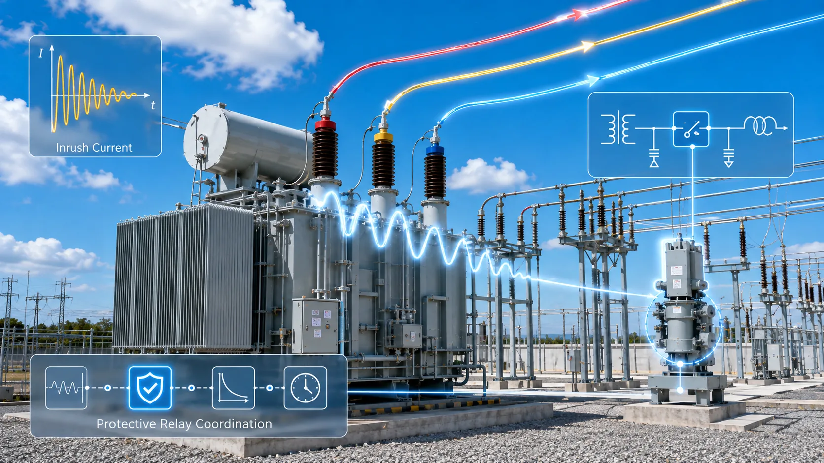
Why magnetizing inrush occurs
At closing, core flux depends on the integral of applied voltage plus residual flux. An unfavorable switching instant can push the core into saturation, sharply reducing magnetizing-branch impedance and producing a large transient current.
Source impedance, transformer characteristics and the magnetic state before closing influence the waveform and decay.
Why differential protection can see a healthy transformer as a fault
During no-load energization, magnetizing current enters mainly from the energized side. In a differential quantity it can resemble internal fault current.
Protection algorithms therefore use current-waveform characteristics, harmonic content and other restraint/blocking logic. The goal is security during normal energization without sacrificing dependability for real internal faults.
Separate “energize the second transformer” from “close the bus tie”
Projects sometimes treat these as one operation. In many schemes the second transformer is energized and stabilized first; paralleling then follows an approved sequence. Other topologies differ. The switching philosophy must be defined by the project design.
If protection settings, CT circuits and energization sequence are discussed only on the final commissioning day, normal inrush can cause avoidable trips—or a real wiring/protection issue can be missed.
Information each party should provide
The buyer/protection engineer should provide the one-line, transformer voltage/kVA, intended energization method, source short-circuit level or equivalent impedance, relay model, CT ratios/connections and protection philosophy.
The transformer supplier should provide rated data, vector group, %Z, contract-required no-load/excitation test data and terminal/CT interface information within its scope. Keep event records and oscillography from first energization and any trip.
Procurement / engineering execution checklist
| Role | Core information / action |
|---|---|
| Buyer / Protection | One-line, energization method, source strength, relay model/settings study, CT ratios/connections and parallel operating mode. |
| Supplier | Transformer ratings, vector group, %Z, contract-required excitation/no-load data and terminal/CT interfaces. |
| Commissioning | Approved switching sequence, protection status, first-energization waveform/event record and any trip report. |
The Transformer Was Healthy. Why Did Protection Trip at Energization?
Frequently Asked Questions
Is magnetizing inrush a transformer fault?
No. It is a possible normal energization transient, but protection must discriminate it correctly.
Is second-harmonic restraint the only way to detect inrush?
No. Waveform and other combined algorithms may be used depending on the relay and protection philosophy.
Does closing a bus tie always create inrush?
Inrush is associated with energizing transformer magnetic flux. If both units are already energized, the tie-closing concerns include phase, voltage difference and circulating current instead.
- Power Transformers and Protection Q&A — operation, paralleling, ratio, vector group, impedance and inrush chapters
- Electrical Engineer’s Handbook, 4th ed. — system connection, transformer impedance and substation engineering
- Relay Protection Technical Supervision Manual — transformer inrush, differential protection and commissioning checks
- Fundamentals of Power Systems — neutral grounding and transformer zero-sequence networks
This article is an engineering and procurement guide. Final paralleling, protection, grounding and switching decisions must follow the project one-line, applicable standards, utility requirements and authorized engineering/commissioning procedures.