Parallel Transformer Troubleshooting: Unequal Current, Temperature, Circulating Current, Neutral Current & Trips
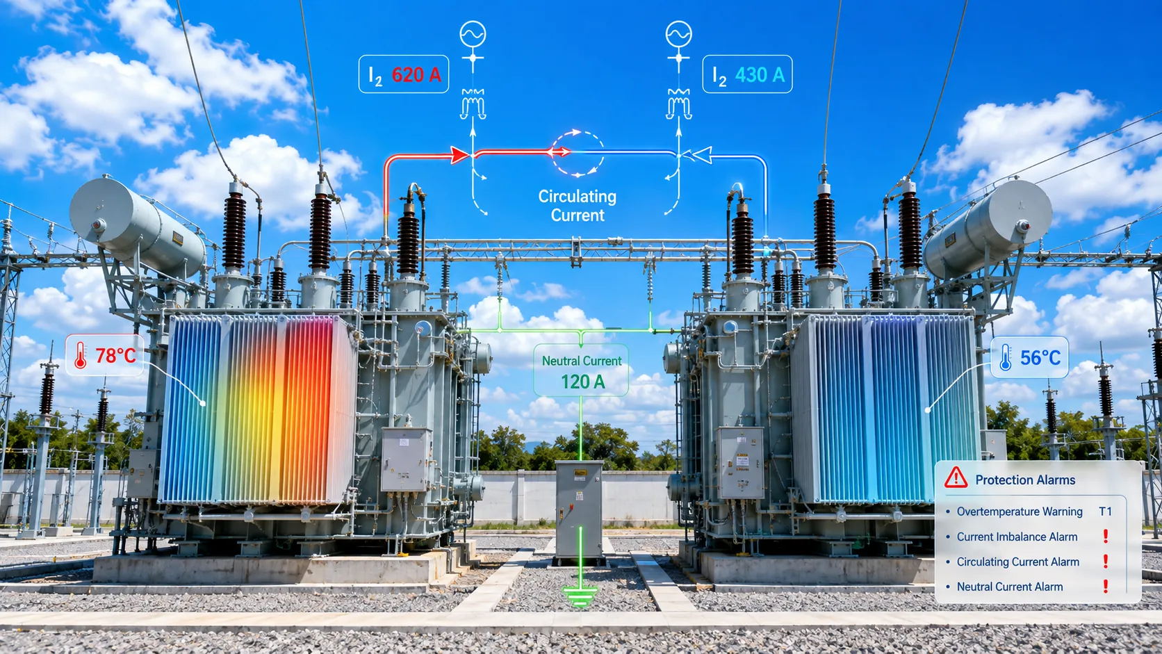
Step 1 — prove the difference is real
Compare meters/CT ratios, measurement timing, ambient temperature, load condition and sensor accuracy. Data from different times or operating points can create a false comparison.
If the hotter unit is also carrying more load, the temperature difference may first be a load-sharing result rather than a cooling failure.
Step 2 — check taps and ratio for circulating current
Compare actual taps, primary/secondary voltage and any history of tap changes. Significant current difference at very light load, or a difference that changes with tap adjustment, points back toward source-voltage mismatch and circulating current.
Step 3 — use kVA and %Z to explain unequal loading
Calculate expected sharing using rated kVA and measured/guaranteed %Z, then compare with field current/kVA. If field behavior follows the predicted trend, the difference may be parameter-driven. If it is much larger than predicted, continue to voltage, phase, connection, measurement and equipment-condition checks.
Step 4 — review phase unbalance, neutral and zero sequence
Compare phase currents and neutral current. A changed zero-sequence path after paralleling can alter neutral and ground-fault behavior. Use the one-line, grounding points, CT locations and load unbalance to interpret it.
Step 5 — put protection events on the timeline
If the event occurs at energization or transfer, review magnetizing inrush, CT transient behavior and switching/protection logic. If it occurs under stable load, focus on actual faults, unbalance, overload or grounding conditions. Relay event reports and oscillography are more useful than a verbal “it tripped once.”
Step 6 — then inspect the transformer and cooling system
After system causes are screened, inspect fans/pumps/radiators, oil level/flow, terminal heating, bushings, winding or core condition as appropriate. This sequence does not ignore equipment faults; it prevents a normal load-sharing difference from being misdiagnosed as a cooling problem.
Build a parallel-operation baseline
Keep both nameplates, tap positions, %Z, ratio/connection test data, phase currents, kW/kVA, bus voltage, neutral current, oil/winding/ambient temperatures, relay events and cooling state from the initial operating period. Future “one unit is always hotter” questions become data comparisons instead of guesses.
Procurement / engineering execution checklist
| Role | Core information / action |
|---|---|
| Operations | Same-time load/current/temperature/neutral data, relay events and ambient conditions. |
| Engineering | Tap/ratio history, expected S/%Z sharing, one-line, grounding/CT paths and energization timeline. |
| Supplier / Service | Manufacturing/test parameters and equipment-condition/cooling evidence after system causes are screened. |
One Transformer Always Ran Hotter. Why Didn’t We Blame Cooling First?
Frequently Asked Questions
Does a hotter transformer automatically have a cooling problem?
No. Compare actual load, impedance-driven sharing, circulating current, ambient and measurement before blaming cooling.
Does unequal current always mean different %Z?
No. Ratio/tap mismatch, unbalanced load, phase/connection issues, measurement and equipment condition can also contribute.
Which historical data is most useful?
FAT/delivery baseline, %Z, ratio/connection, taps, first-parallel currents/temperatures/neutral current and relay events.
- Power Transformers and Protection Q&A — operation, paralleling, ratio, vector group, impedance and inrush chapters
- Electrical Engineer’s Handbook, 4th ed. — system connection, transformer impedance and substation engineering
- Relay Protection Technical Supervision Manual — transformer inrush, differential protection and commissioning checks
- Fundamentals of Power Systems — neutral grounding and transformer zero-sequence networks
This article is an engineering and procurement guide. Final paralleling, protection, grounding and switching decisions must follow the project one-line, applicable standards, utility requirements and authorized engineering/commissioning procedures.