Satellite Article #1 · Pad-Mounted Transformer Series
Loop Feed vs Radial Feed: Which One Should the Project Specify?
Loop feed vs radial feed is not a catalogue choice. It is a decision about the single-line diagram, cable route, normal open point, switching sequence, through-current rating and utility operating procedure.
Direct Answer: Radial Feed or Loop Feed?
Specify radial feed when the pad-mounted transformer is the final unit on one medium-voltage feeder and the project accepts an outage when that feeder is isolated or fails.
Specify loop feed when the single-line diagram requires both incoming and outgoing medium-voltage cable connections and the operating plan uses sectionalizing or an alternate route to restore supply.
Loop feed is not automatically redundant. The second cable path, source arrangement, switch scheme, protection settings, ratings and utility operating procedure must all support the intended restoration plan.
The specification rule: do not compare the loop-feed premium with radial feed until the project has confirmed the SLD, normal open point, switching sequence and through-current rating.

Engineering Scenario: The Buyer Ordered Six Bushings—but Not a Restoration Plan
Illustrative scenario: this is an engineering education scenario, not a claim about a completed TransformerGrid project.
A project team wants to reduce downtime, so the RFQ asks for a “loop-feed pad-mounted transformer.” The buyer compares quotations, confirms six primary connection positions and awards the order. On paper, the equipment appears to provide two cable directions.
Then the commissioning team asks a simple question: if the cable between Transformer 1 and Transformer 2 fails, which devices will be opened, where is the normal open point, and from which direction will the healthy section be re-energized?
The RFQ has no answer. The SLD shows an outgoing cable, but it does not define the alternate source, switching sequence, protection conditions or feeder through-current. The project bought the appearance of loop feed before proving the function of loop operation.
This is the mistake this guide is designed to prevent. The buying decision is not “three bushings or six.” It is whether the transformer connection, external network and approved operating procedure form one workable restoration plan.
Loop Feed vs Radial Feed at a Glance
| Project question | Radial feed | Loop feed |
|---|---|---|
| Medium-voltage cable paths at the transformer | One incoming path; transformer is normally a terminal point | Incoming and outgoing paths; transformer is a node in the feeder loop |
| Typical three-phase dead-front primary interfaces | Three primary connection positions | Six primary connection positions |
| Alternate supply route | Not provided by the transformer connection | Possible only when the external network and operating plan provide it |
| Isolation and restoration | Normally requires interruption of the single feeder section | Can support sectionalizing and restoration from another direction, depending on switch design and utility practice |
| Main advantage | Simpler equipment and site arrangement | Greater operating flexibility and easier feeder sectionalizing |
| Main risk | A single feeder fault or planned isolation interrupts the transformer | Extra interfaces and switching do not create reliability unless the system is correctly designed and operated |
| Best fit | Standalone loads, terminal transformers, projects with acceptable outage windows | Campus distribution, multiple-transformer feeders, utility loops and sites with a defined alternate supply path |
Typical arrangements are shown for three-phase dead-front pad-mounted transformers. The utility specification and approved drawings control the final layout.

What Is a Radial-Feed Pad-Mounted Transformer?
A radial-feed transformer is connected at the end of one medium-voltage feeder. On a typical three-phase dead-front unit, the primary compartment has three phase connection positions for the incoming cable.
Radial feed is often the correct choice when:
- the transformer is the last device on the feeder;
- no outgoing medium-voltage cable is shown on the SLD;
- the utility operates the site as a radial system;
- a planned outage is acceptable for cable or transformer work;
- a separate external switching arrangement already provides the required isolation; or
- the cost and space of a second cable route cannot be justified by the project.
Radial does not mean inferior. It means the project has chosen a single supply path at that transformer location.
What Is a Loop-Feed Pad-Mounted Transformer?
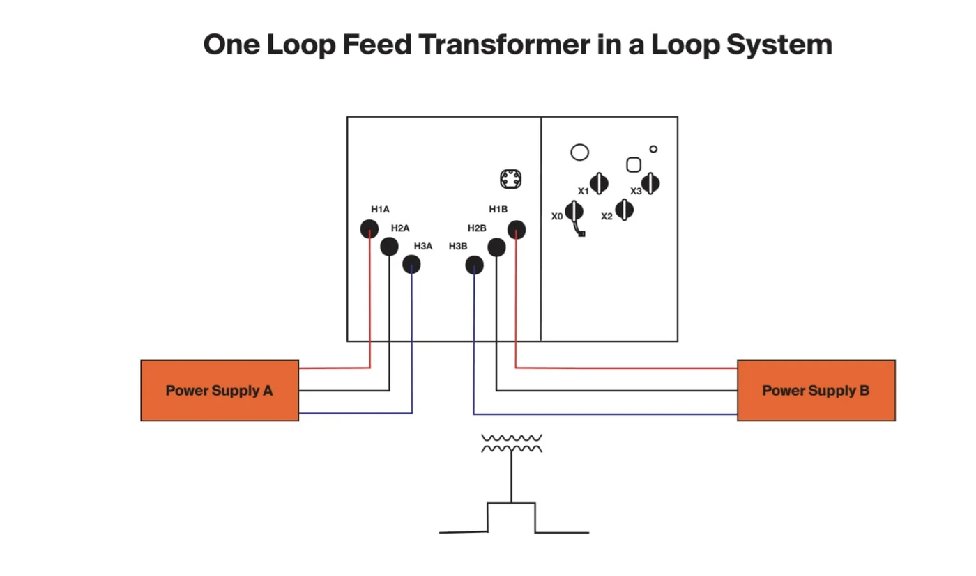
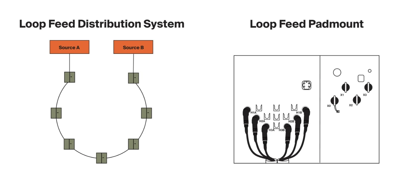
A loop-feed transformer has primary connections for both incoming and outgoing feeder cables. A typical three-phase dead-front layout therefore has six primary connection positions: three for one cable set and three for the other.
The transformer can then sit within a looped underground distribution system. Depending on the external network and switching scheme, crews may isolate a faulted cable section and restore unaffected sections from another direction.
Loop feed is worth serious consideration when:
- the SLD shows the feeder continuing to another transformer;
- several pad-mounted transformers share an underground distribution loop;
- the utility specification requires a loop-feed compartment arrangement;
- the owner needs a defined restoration path during cable maintenance;
- future expansion will continue the medium-voltage feeder beyond this unit; or
- the project has documented the financial or operational consequence of a feeder outage.
However, six primary interfaces alone do not prove that the system can maintain service. The project must also confirm the switch arrangement, cable route, normal open point, alternate source availability, feeder protection and operating authority.
The Decision Is Made on the SLD, Not in the Transformer Catalogue
Before asking a manufacturer for a loop-feed quotation, read the single-line diagram in this order.
1. Trace the incoming medium-voltage source
Identify the upstream protective device, conductor or cable rating, nominal voltage, grounding method and available fault-current information.
2. Check whether the feeder ends or continues
If the cable terminates at the transformer, the drawing indicates a radial application. If another cable leaves the transformer location and continues to another unit or source point, the physical arrangement is loop feed or feed-through.
3. Locate the normal open point
Many distribution loops are operated with an open point to avoid unintended paralleling and to keep protection coordination manageable. The SLD or operating diagram should state where the loop is normally open and who is authorized to change it.
4. Write the required restoration sequence
Ask what happens after a fault between two transformer locations. Which devices are opened? Which cable section remains isolated? From which direction can unaffected loads be restored? If the team cannot describe the sequence, “loop feed” is not yet a complete requirement.
5. Check every component in the through path
The outgoing cable, bushings or inserts, internal bus, switch and connectors must be rated for the feeder duty they carry. That duty may include downstream load and can be different from the transformer winding primary current.

Why Bushing Count Alone Is Not Enough
The old shorthand is useful but incomplete: radial feed often means three primary connection positions; loop feed often means six primary connection positions. Procurement must go further.
A complete specification identifies:
- dead-front or live-front construction;
- interface type and voltage class;
- continuous-current rating of the feeder interfaces;
- short-time and fault-closing duties where applicable;
- switch type, positions and operating rating;
- bushing and cable orientation;
- phase identification and parking provisions;
- surge arrester arrangement;
- interlocks, operating handles and nameplate diagram; and
- utility-approved normal and emergency operating states.
Three-phase pad-mounted transformers can be offered with radial or loop-feed arrangements and optional internal oil switching. The exact combination is selected for the project; it should never be inferred from the words “pad-mounted transformer” alone.
Does Every Loop-Feed Transformer Need a Four-Position Switch?
No. “Loop feed” describes the feeder connection arrangement; it does not define one universal switch package.
Possible project arrangements include:
- feed-through connections with switching performed by separate equipment;
- individual switches that isolate the transformer branch while maintaining feeder continuity;
- sectionalizing switches that provide multiple feeder states; or
- integrated protection and switching packages designed for a specific utility scheme.
The number of switch positions is not a reliable purchasing shortcut because manufacturers use different mechanisms and operating diagrams. The RFQ should attach or request the switch schematic and state the required operating sequence. The approved drawing and nameplate must identify every switch position unambiguously.
Procurement warning: never describe “loop closed” as the normal state unless the utility-approved study permits the relevant sources or feeder sections to be paralleled.
How Should the Project Select 200 A or 600 A Interfaces?
Do not select the interface current rating from transformer kVA alone.
For a radial transformer, the primary winding current is one relevant input. In a loop-feed unit, the feed-through path may also carry the current of downstream transformers. The project should therefore calculate or obtain:
- maximum feeder load current;
- expected downstream expansion;
- emergency or transfer loading;
- cable ampacity;
- connector and bushing-interface rating;
- switch continuous-current rating;
- available fault current and required short-time duty; and
- local utility standard.
A small transformer can occupy an upstream position in a loop carrying much more feeder current than its own winding draws. This is why “500 kVA means 200 A” is not a safe universal rule.
Reliability: What Loop Feed Can and Cannot Do
What loop feed can do
- provide an alternate route to unaffected sections;
- allow a damaged cable segment to be isolated;
- improve switching flexibility during planned work;
- support future feeder extension; and
- reduce the number of loads affected by one cable-section outage.
What loop feed cannot do by itself
- create a second source where none exists;
- guarantee uninterrupted power during every fault;
- replace protection-coordination and fault-duty studies;
- make an incorrectly rated cable, connector or switch safe;
- authorize paralleling that the utility prohibits; or
- eliminate the need for qualified switching procedures.
The correct comparison is therefore not “three bushings versus six bushings.” It is “one defined operating plan versus another.”
Cost Comparison: Request a Project-Specific Delta
Avoid generic percentage premiums and catalogue-style component prices. The cost difference depends on the voltage class, interface rating, switch package, protection, enclosure layout, cable terminations and site work.
Ask bidders to separate the comparison into the following scope:
| Cost scope | Radial quotation | Loop quotation | Buyer check |
|---|---|---|---|
| Transformer primary interfaces | Included | Included | Type, class, current and quantity clearly stated |
| Internal switching | As specified | As specified | Schematic and ratings attached |
| Internal bus and leads | Included | Included | Through-current rating confirmed |
| Cable elbows/connectors | State inclusion | State inclusion | Avoid comparing quotations with different accessory scope |
| Surge arresters and parking stands | State inclusion | State inclusion | Match utility arrangement |
| Additional MV cable and terminations | Site scope | Site scope | Route length and trench work confirmed |
| Testing and documentation | State inclusion | State inclusion | Switch-operation and continuity records requested |
Then compare the quoted delta with a project-specific outage and restoration assessment. Do not approve an ROI claim until both sides of that calculation are documented.
Three Engineering Decision Scenarios
These scenarios are engineering decision models. They are not presented as completed customer projects.
Scenario A: The lowest quotation is also the correct one
One transformer supplies a standalone commercial building from one utility cable. The SLD has no outgoing feeder, and the owner accepts a planned outage for maintenance. A bidder proposes loop feed “for better reliability,” but no second route exists outside the transformer. In this case, radial feed is normally the clearer specification unless the utility requires otherwise.
Scenario B: Six interfaces support a real restoration sequence
An underground feeder enters the first transformer location, continues through several campus buildings and reconnects to an alternate supply point. The owner has identified the normal open point and documented how crews will isolate one faulted section before restoring the healthy loads from the other direction. Here, loop-feed equipment is likely appropriate, but every interface, internal bus and switch must be rated for the full feeder duty at its location.
Scenario C: Two words in a meeting create an expensive assumption
During a meeting, the owner says, “future expansion.” The phrase is copied into the RFQ, and loop feed is added as insurance. Yet the present SLD shows no future cable route, alternate source, load estimate or protection plan. Do not specify loop feed from those two words alone.
What Must Be Written in the RFQ?
| RFQ field | What the buyer should state |
|---|---|
| Feed configuration | Radial feed or loop feed |
| System diagram | Attach current SLD and site feeder layout |
| Primary system | Nominal voltage, maximum system voltage, grounding method and BIL/insulation requirements |
| Construction | Dead-front or live-front; required interface type |
| Interface current | Continuous-current rating based on feeder duty |
| Switching | Required schematic, positions, load-break/non-load-break duty and operating sequence |
| Protection | Upstream device, transformer protection, available fault current and coordination requirements |
| Cable arrangement | Incoming/outgoing direction, phasing, cable size, elbow/connector scope and parking provisions |
| Utility requirements | Utility specification, approved-material requirements and drawing comments |
| Verification | Required drawings, nameplate diagram, continuity checks, switch-operation checks and pre-shipment photographs |
Sample RFQ wording
Three-phase pad-mounted transformer, loop-feed primary arrangement. Provide incoming and outgoing primary interfaces and switching in accordance with the attached SLD and utility specification. Manufacturer shall state interface voltage/current ratings, through-current rating, switch make/model and operating diagram. Final production is subject to buyer approval of the primary-compartment layout, phasing and nameplate switch diagram.
This wording is a starting point, not a substitute for the project engineer’s specification.

Drawing-Approval Checklist Before Production
Before signing the outline and terminal-compartment drawing, verify:
- radial or loop feed is stated in words;
- the drawing matches the SLD;
- incoming and outgoing cable directions match the site plan;
- phase labels match the project convention;
- interface type, voltage class and current rating are shown;
- the feed-through path rating is confirmed;
- the switch schematic and every handle position are shown;
- the normal open point is identified in the operating documents;
- surge arresters, parking stands and grounding points are located;
- cable bending space and termination access have been reviewed;
- protection and fault-duty inputs have been supplied; and
- FAT/document requirements include the relevant continuity and switch checks.
Send Your SLD Before You Compare the Price
The highest-value step occurs before quotation, not after the transformer reaches the site. Send TransformerGrid the current SLD, utility specification and site feeder layout. The review can identify whether the drawing shows a terminal or feed-through location, which ratings require confirmation, whether bidder scope is comparable and which compartment drawings should be approved before production.
TransformerGrid does not replace the engineer of record or the utility’s operating authority. The purpose of the review is to expose specification gaps before they become quotation differences, drawing revisions or site rework.
Suggested data: SLD + utility specification + project country + primary voltage + transformer kVA + incoming/outgoing cable layout.
Frequently Asked Questions
Is loop feed always better than radial feed?
No. Loop feed is useful only when the external network, switching plan and operating procedure can use the second cable path. A terminal transformer on a genuinely radial system gains no automatic reliability from six primary interfaces.
Can a loop-feed system be operated radially?
Yes. Many looped distribution systems are operated with a normally open point, so each section is radial in normal operation while the alternate path is reserved for restoration. The utility-approved SLD and operating procedure control the actual arrangement.
Can a radial-feed transformer be converted to loop feed in the field?
Usually this is not a practical field conversion. Adding primary interfaces, internal buswork, tank penetrations, switching, labels and tests changes the factory design. Treat future loop requirements during specification and drawing approval rather than assuming a later retrofit.
Is a loop-feed transformer the same as an RMU?
No. A loop-feed transformer is still a transformer with feed-through primary connections and possibly integrated switching. A ring main unit is medium-voltage switchgear. Some projects combine switching and transformation in one assembly; others use separate equipment.
Does loop feed require a four-position switch?
Not universally. The required switch arrangement depends on the utility scheme and desired isolation/restoration sequence. Specify the operating states and ratings, then require the manufacturer’s schematic.
Should the project choose 200 A or 600 A from transformer kVA?
No. Select the interface and switch ratings from feeder current, downstream load, cable rating, expansion, fault duty and utility requirements. The feed-through path can carry more current than the transformer winding itself.
Which standard should the RFQ reference?
For North American three-phase pad-mounted distribution transformers, the project may reference the applicable edition of IEEE C57.12.34 together with the utility specification and other required IEEE standards. Standards do not by themselves select radial/loop configuration, switch logic or accessories; state those explicitly and attach the approved SLD.